
How to Achieve a Perfect Selective Soldering Result: A Three-Stage Process Breakdown
Leo Peng | Sasinno | Selective Soldering Process Engineering
A practical engineering guide to the three stages of selective soldering — spray fluxing, pre-heating, and soldering — aligned to IPC-A-610 and IPC J-STD-001 acceptance criteria for through-hole barrel fill.

Sasinno selective soldering machine in production
IN THIS ARTICLE
· Introduction — Why "Perfect" Is a Process, Not a Single Action
· Stage One — Spray Fluxing: The First Drop Decides the Joint
· Stage Two — Pre-heating: The Stage Everyone Underestimates
· Stage Three — Soldering: Where the Physics Gets Final
· Closing — Three Stages, One Outcome
Introduction: Why "Perfect" Is a Process, Not a Single Action
A selective soldering line looks deceptively simple from the outside — a board enters, a nozzle touches it, a joint forms, the board leaves. But behind every IPC-compliant through-hole joint on that board sits a tightly choreographed three-stage process: flux application, pre-heating, and soldering. Skip or weaken any one of these stages, and the result is no longer "soldering" — it is gambling with yield.
This article breaks the process down the way Sasinno’s engineering teams think about it: stage by stage, parameter by parameter, and — where it matters — against the acceptance criteria defined by IPC-A-610 and IPC J-STD-001. The goal is not to sell a feature list, but to make clear why each stage exists, what goes wrong when it is neglected, and how the equipment you choose determines whether your process can hold the line at 75% barrel fill — or whether it quietly drifts below it.
Throughout, we will refer to the Sasinno Ultra series of selective soldering machines, because that is where these principles have been engineered into hardware rather than left as operator discipline.
Stage One — Spray Fluxing: The First Drop Decides the Joint
Why Flux Application Comes First — and Why the Method Matters
Flux is not a "helper" in soldering; it is a precondition. Its job is to remove oxide from the pad and the plated barrel wall, lower surface tension, and allow the molten solder to wet and climb. No flux in the barrel, no climb. No climb, no IPC-compliant fill.
On a selective soldering machine, flux can be applied in several ways — foam, brush, or jet. Sasinno’s Ultra series uses drop jetting: a high-frequency jet valve that fires discrete droplets of flux onto the board. The decisive advantage of drop jetting over brushing or foaming is that the flux does not just sit on the pad surface — it penetrates into the plated through-hole barrel.

Drop jet flux nozzle applying flux to through-hole barrel
Why Penetration Into the Barrel Matters — The IPC 75% Rule
Consider a 2 mm thick board. To meet the 75% criterion, solder must fill the barrel to a height of 1.5 mm. That solder has to climb from the bottom side, against gravity, through a plated tube that is colder the higher it goes. If the flux has only been deposited on the bottom pad and has not reached the inner wall of the barrel, the oxide inside the barrel is still there — and solder will not wet a surface it cannot chemically bond to. The climb stops short. The joint fails fill.
Drop jetting solves this by driving flux not just onto the pad but into the hole, so that the entire barrel wall is activated before the solder wave arrives. This is the first physical precondition for hitting the 75% number consistently.
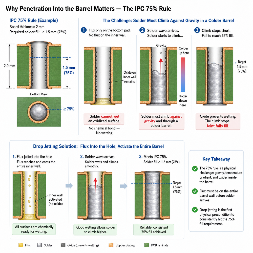
Through-hole barrel cross-section, 75% solder fill per IPC-A-610
Sasinno Ultra’s Three Engineering Decisions on Flux
· 1. High-frequency drop jet valve. The valve opens and closes at very high frequency, producing controlled droplet deposition rather than a continuous stream. This allows precise targeting of pads and holes without overspraying adjacent SMD components — a key reason selective soldering exists in the first place.

· 2. Per-board flux volume statistics — catching partial clogs before they become failures. Most machines on the market detect a flux fault by asking a binary question: is flux still coming out of the nozzle? As long as the answer is "yes," the machine stays quiet. The problem is that a jet nozzle with an orifice of only 0.11 mm or 0.13 mm does not fail abruptly — it degrades. A tiny contaminant builds up, and the discharge drops from 100% to 70% before the nozzle is fully blocked.
Consider a board we will call Sample A. Normally it receives 10 mg of flux per cycle. After some hours of production, the Ultra’s per-board statistics report that Sample A is now only receiving 7 mg — a 30% reduction. The nozzle has not fully blocked; flux is still exiting; a conventional "is-there-flux" sensor would see nothing wrong. But the process is already drifting. Less flux reaches the pad, less reaches the barrel, and the next batch of joints is quietly falling below the 75% fill line.
By measuring volume instead of presence, the Ultra series turns a silent yield loss into a visible, trendable data point. Maintenance can be scheduled before the defect, not after a rejection pile forces it.
· 3. One-switch auto-clean — making nozzle maintenance a button press, not a teardown. The same small orifice that makes jetting precise also makes it vulnerable to clogging from dried flux and particulates. The Ultra series addresses this with a one-touch switch from flux to cleaning fluid: at the end of each production day, the machine prompts the operator to run an automatic nozzle flush. The operator presses one button; the valve cycles cleaning fluid through the nozzle; the orifice is cleared without manual disassembly. The point is not that cleaning is unusual — it is that Sasinno made it cheap enough to actually happen every day.
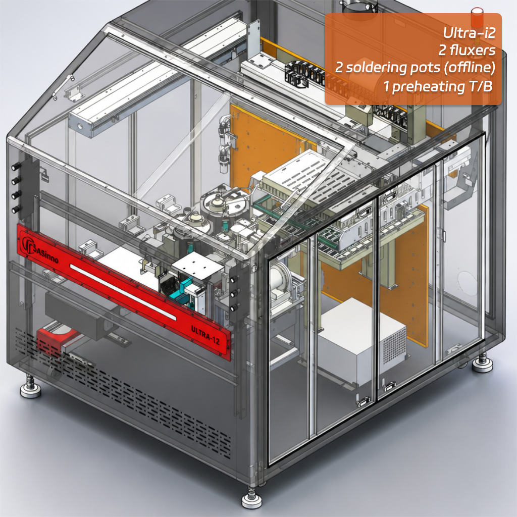
Ultra-i2 configuration: drop jet fluxers, solder pots and preheating modules
Stage Two — Pre-heating: The Stage Everyone Underestimates
The Real Job of Preheat Is Chemical, Not Just Thermal
Pre-heating is the most frequently underestimated stage in selective soldering — and, conveniently, the one most often dismissed by equipment manufacturers who do not include it as standard.
The core function of preheat is to drive off the volatile components of the flux, and in doing so, to remove the oxide layer from the pad and barrel surface. When the solvent and activator volatiles leave, they carry surface oxides with them. Only after this happens can the incoming solder form a true metallurgical bond with the pad and barrel — what IPC refers to as evidence of wetting and adhesion, with a wetting angle not exceeding 90°.
If preheat is missing or insufficient, the oxide stays, and the solder sits on top of the oxide rather than bonding to the copper. You get a joint that looks soldered but has no real fillet strength — a cold joint under IPC criteria, classified as a defect in Class 2 and Class 3.

Top and bottom preheat modules on Sasinno Ultra
Why Both Top and Bottom Preheat Matter
Sasinno’s Ultra machines apply heat from both above and below the board. Each side has a distinct job.
Bottom preheat — applied to the fluxed side — performs the volatilization and oxide removal described above.
Top preheat exists for a different but equally critical reason: to minimize the temperature gradient across the board thickness. There are two consequences of ignoring the top side:
Board warpage. A large ΔT between the bottom (heated) and top (ambient) surfaces creates differential expansion, and on a thick or large panel this warps the board — pulling pads out of alignment with the nozzle and degrading joint geometry.
Premature solder freezing inside the barrel. This directly affects the 75% fill. Imagine a 2 mm board where the bottom is preheated to 150°C but the top surface is still at room temperature (25°C). When the solder wave touches the bottom of the barrel at 150°C and begins to climb, the barrel gets colder the higher the solder goes. At some point the solder hits a wall of cold copper and freezes mid-barrel. The climb stops. The fill falls short of 75%. The joint is rejected.
Top preheat keeps the entire barrel warm enough that the solder can complete its climb before solidifying. This is the physical reason preheat is not optional for thick or heat-sinking boards.
Preheat Temperature Range and What Drives It
Typical bottom-side preheat lands in the 100°C to 150°C range. The exact setpoint depends on:
· Flux type — different chemistries activate and volatilize at different temperatures
· Board thermal mass — thickness, layer count, copper pours
· Board material — FR-4 Tg, laminate type
· Component density and distribution — how much heat the populated board absorbs
There is no universal setpoint; the range is where the engineering begins, not where it ends.
What Happens When Preheat Is Skipped — Solder Balls
When a board is not adequately preheated, certain flux chemistries will produce solder balls — small discrete spheres of solder scattered on the board surface after the joint is formed. The mechanism is straightforward: flux contains moisture and volatile solvents. If preheat has not driven them off, those volatiles remain. When the molten solder wave then contacts them, the trapped moisture flashes to steam and explodes through the solder, ejecting tiny droplets that solidify as balls.
Solder balls are not cosmetic. They are a serious downstream defect — they can bridge fine-pitch traces, cause intermittent shorts, and are difficult to detect and remove in later stages. Their root cause is almost always the same: preheat was neglected.
Sasinno’s Position on Preheat — and Why It Is Not Standard Elsewhere
Here is where the market gets uncomfortable. Most competing selective soldering machines in the same tier do not include preheat as standard equipment — and some manufacturers actively tell customers that preheat is unnecessary in selective soldering, or that nitrogen-only preheat is a substitute.
Nitrogen can play a preheat role, but nitrogen-based heating is point-by-point — it heats only where the nozzle currently sits. On any board with more than a handful of joints, this makes the cycle extremely slow. It is not a substitute for a board-wide top-and-bottom preheat stage.
Sasinno’s stance is the opposite: preheat is standard across the entire Ultra lineup, including:
· Ultra-i1 — offline machine with top and bottom preheat as standard
· Ultra-i2 — offline machine with top and bottom preheat as standard
· Star-1 — the entry-level benchtop model, the most economical machine in the range, still with bottom preheat as standard
The principle is simple: because preheat is critical to the joint, it should not be an option you have to pay extra to unlock.
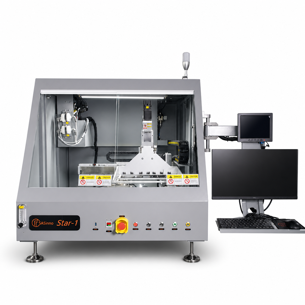
Star-1 benchtop selective soldering machine, bottom preheat standard
Two-Stage Preheat for High-Throughput, Thick-Board Applications
On inline machines, the process flow is spray → preheat → solder, and the preheat stage is typically the longest in the cycle. For thick boards with high thermal mass, a single preheat stage may not bring the board up to temperature along a controlled ramp — the board simply does not have enough residence time to reach a stable preheat profile before it meets the solder wave.
To address this, certain Sasinno inline models offer two-stage preheat — extending the preheat zone so the board sees a longer, gentler ramp. This is, to our knowledge, not commonly offered in this class of equipment. The models equipped for this are:
· Ultra-i2/52 — high volume with longer preheat
· Ultra-i4/52 — highest capacity high volume model with two-stage preheat
These are targeted at high-throughput lines running thick, heat-sinking boards where a single preheat zone would compromise the cycle-time balance of the spray–preheat–solder sequence. The goal of the two-stage design is to maintain the line’s cycle balance — you do not gain a fast soldering stage if preheat becomes the bottleneck.
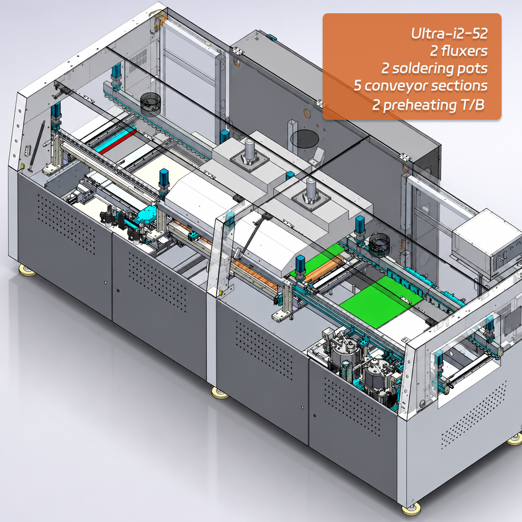
Ultra-i2/52 inline machine with two-stage preheat configuration
Stage Three — Soldering: Where the Physics Gets Final
Even with perfect flux and perfect preheat, the third stage — the soldering itself — can still undo everything. Four parameters determine whether the joint forms correctly at the wave.
Parameter 1: Solder Temperature — Higher Than Wave Soldering, for Good Reason
Selective soldering typically runs at a higher set temperature than wave soldering. The reason is geometric: a wave solder bath presents a large area of molten solder to the board, transferring heat broadly; a selective solder nozzle presents a single small column of solder to one joint at a time. To deliver the same thermal energy to the pad and barrel through a smaller contact area, the solder itself must be hotter.
This has two direct equipment consequences:
· The solder pot and wetted components must be made of more thermally robust materials, because they live at a higher temperature continuously.
· The solder surface must be protected by nitrogen. At elevated temperatures, oxidation of the solder surface accelerates rapidly. Without an inert atmosphere blanket over the solder wave, oxide forms on the meniscus, gets drawn into the joint, and produces defects — inclusions, poor wetting, and inconsistent fillet geometry.
A machine that runs hot but does not manage oxidation is not producing selective soldering; it is producing oxidized joints at scale.
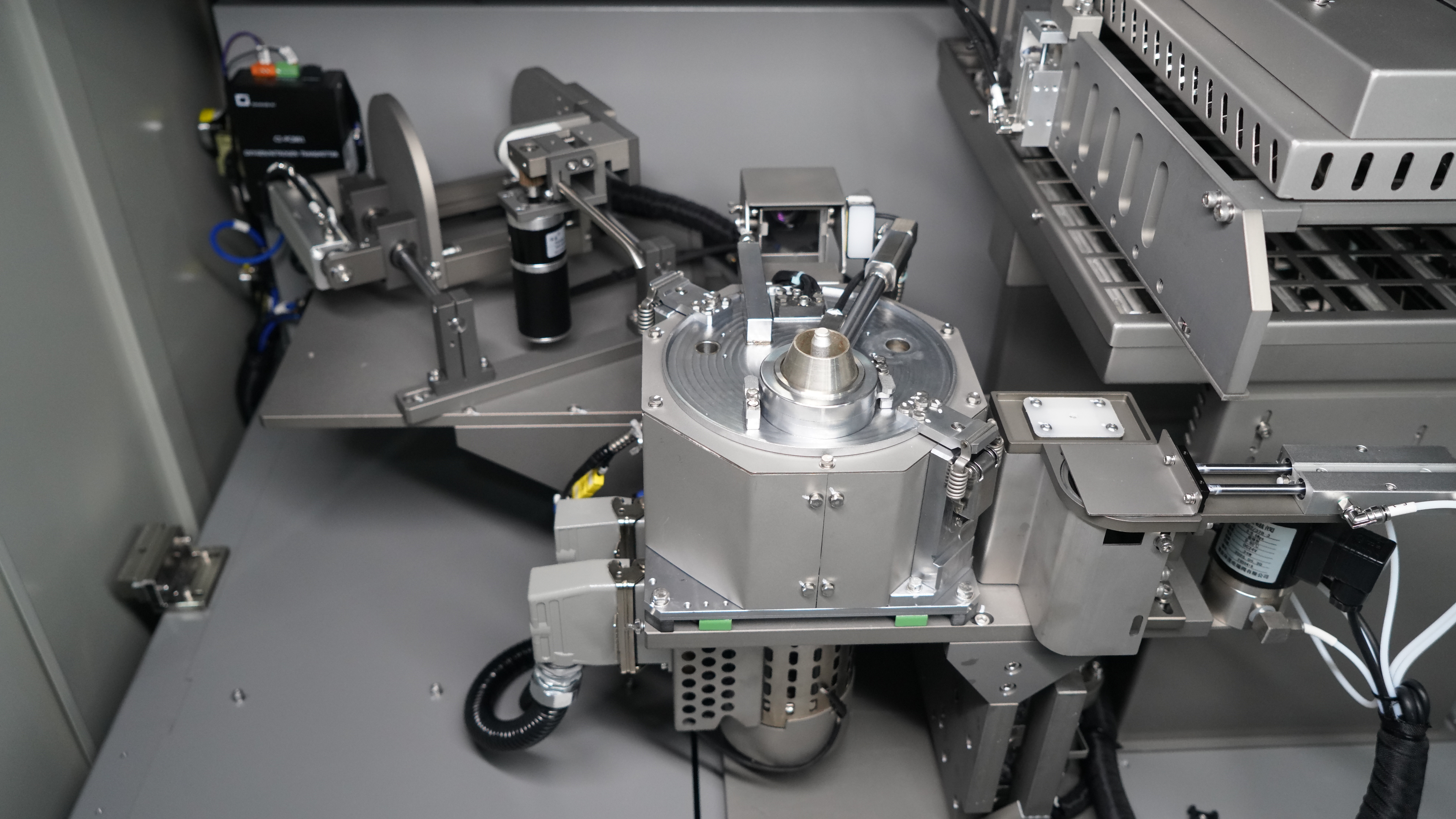
N2 heater protecting the molten solder surface on Sasinno Ultra
Parameter 2: Wave Height Stability
A selective solder wave must hold its height. If the wave is 10 mm at the start of a run and collapses to 2 mm partway through, every joint soldered during that drift is being formed at a different thermal and mechanical condition. The result is inconsistent fill, inconsistent fillet, and a process that cannot be qualified.
Sasinno’s Ultra series manages wave stability in two ways:
First, the wave generator itself is designed for stability. The pump and nozzle geometry produce a consistent mini-wave under normal conditions.
Second, the machine compensates for solder consumption. As boards are soldered, the solder level in the pot drops, and a dropping level reduces wave height. The Ultra series runs an automatic wave-height calibration routine: at programmed intervals — every N boards — the machine measures and recalibrates the wave height, compensating for the consumed solder volume. The wave you program at the start of the shift is the wave the last board of the shift receives.
Parameter 3: Wave Uniformity and Nozzle Wettability
A selective solder wave does not flow in one direction — it flows 360° around the nozzle, radially outward and downward. For the joint to form symmetrically, that radial flow must be uniform. If the flow is heavier on one side, the joint forms unevenly: one side of the barrel fills, the other does not.
Wave uniformity depends almost entirely on the wettability of the nozzle’s outer surface. If the nozzle wets evenly, the solder film clings uniformly and the wave is symmetric. If the nozzle de-wets — if solder pulls away from one area of the surface — the flow distorts, the wave goes asymmetric, and joints on that side of the nozzle degrade.
This is where nozzle surface treatment becomes the deciding factor. The Sasinno Ultra nozzles use a proprietary multi-layer coating: a total of four layers, each deposited by a different electroplating process. The purpose of the multi-process approach is not cosmetic — it is to achieve two performance characteristics that a single coating cannot deliver simultaneously:
· Long-lasting wettability. The coating keeps the nozzle surface wetting uniformly over extended production runs. When flow eventually does drift, a simple cleaning restores it, and because of the coating’s durability, the interval between cleanings is significantly longer than with standard nozzles.
· Long service life. The coating thickness is engineered for wear resistance. A nozzle that de-wets after half an hour is a production liability; a nozzle that holds its wettability across a long campaign is a process control.
The coating is not a marketing feature; it is the physical reason the wave stays uniform.

360-degree uniform radial solder mini-wave around a selective nozzle
Parameter 4: Dual Solder Pots — Matching Nozzle to Joint
A real production board does not have one type of joint. It has large through-hole connectors — dual- or triple-row pin headers — that require substantial thermal input to fill, and it has small joints between adjacent SMD components, where there is no physical clearance for a large nozzle.
A large nozzle delivers the heat mass the connector needs; a small nozzle fits into the gap the SMD layout allows. One nozzle cannot serve both well.
This is why a well-designed selective soldering machine offers dual solder pots — two independently programmable solder sources, each with its own nozzle. The operator can configure them as one large and one small, and the program routes each joint to the appropriate pot.
In the Sasinno Ultra range, the dual-pot configuration is standard on:
· Ultra-i2 — offline platform with dual solder pots, both electromagnetic-pump driven
· Ultra-i2/41 — inline machine with dual solder circuit, high volume standard throughput
· Ultra-i2/52 — inline machine with dual solder circuit, high volume with longer preheat
The electromagnetic pump is worth noting: it avoids the impeller wear and solder contamination issues associated with mechanical pumps, and it provides more precise control over wave dynamics.
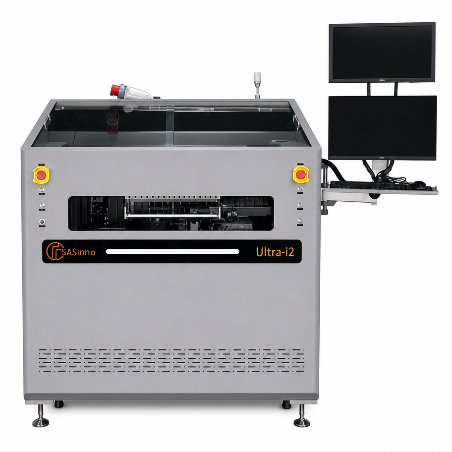
Ultra-i2 offline machine with dual electromagnetic-pump solder pots
Closing: Three Stages, One Outcome
A perfect selective soldering result is not the product of a good solder wave. It is the product of three stages, each of which can independently determine whether the joint meets IPC-A-610’s 75% fill criterion or falls below it.
Fluxing decides whether the barrel wall is chemically ready to be wetted. Without flux in the barrel, the 75% climb has nowhere to start.
Pre-heating decides whether the solder can actually complete that climb — by removing oxide, keeping the barrel warm enough to prevent premature freezing, and eliminating the moisture that causes solder balls.
Soldering decides whether the heat, the wave, the nozzle, and the pot configuration can deliver a consistent joint at every location on the board, from the largest connector to the tightest SMD gap.
What Sasinno’s Ultra series does is not to add features to a generic machine. It is to engineer each of these three stages so that the process is controlled by the equipment — not by the operator’s vigilance, not by luck, and not by a sensor that only reports a failure after the damage is done.
That is what "perfect selective soldering" means in practice: not a single good joint, but a process that produces the same good joint on the first board and the last.
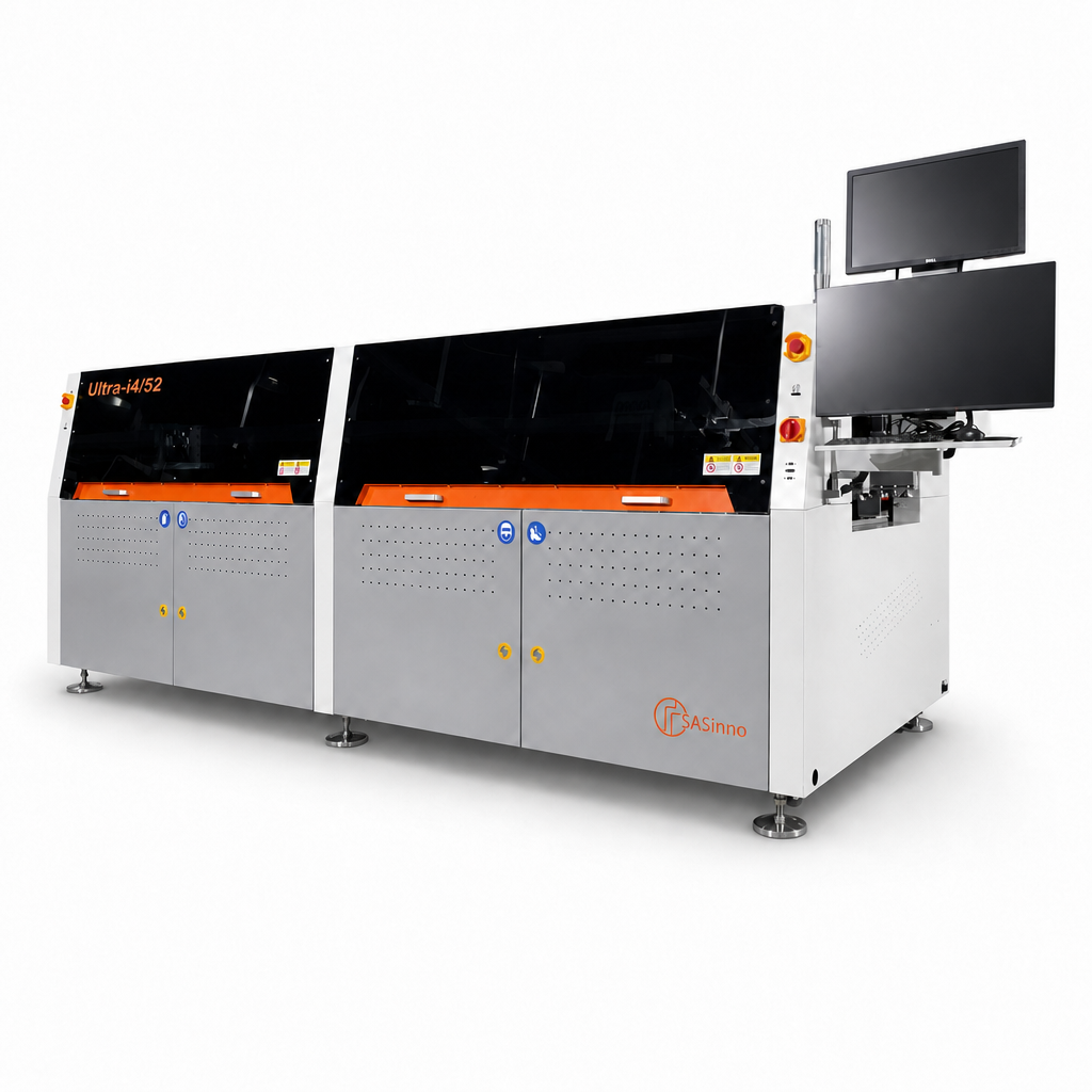
Ultra-i4/52 high-volume inline selective soldering machine
图11 · Ultra-i4/52 机型图 · Alt: Ultra-i4/52 high-volume inline selective soldering machine
About the Author
Written by Leo Peng, Sasinno — Technical Article on Selective Soldering Process Engineering
Related Products / CTA
For more on the Sasinno Ultra series, including the Ultra-i2 offline platform and the Ultra-i2/52 and Ultra-i4/52 inline platforms with two-stage preheat, visit sasinno.com/products.